The motor terminal connection in the case of star and delta is shown in the above figure where U1 V1 W1 is the start terminal of each winding and U2 V2 W2 is the finish of each winding. Drawing the schematic diagram of AC.

Autotransformer Starter Diagram Parts Working Principle Etechnog
Figure 2 delta delta transformer connections click to expand diagram.
. Readers are encouraged to identify these in. The ABB autotransformer starter is a closed transition type meaning that the motor remains connected to the. Drawing the schematic diagram of automatic voltage regulators of AC.
In this post we are going to know the details of each part of DOL Starter DiagramAll parts of the DOL starter Power Circuit Diagram and Control Circuit Diagram are explainedDirect Online Starter or DOL Starter is very useful and commonly used AC StarterDOL starters are mainly used with up to 5 HP motors. Electrical Electrical Machine Induction Motor Motor Starter. I B Make a list of components used.
14 Schematic Diagram Of Transformer. Auto transformer starters are used generally with AC squirrel cage motors having a power rating of more than 20 HP. A s tar delta starter is a type of reduced voltage starter.
The transformer works on the principle of Faradays law of electromagnetic induction and mutual induction. Let Z e10 is the equivalent standstill impedance per phase of the motor referred to the stator side. Theory of Autotransformer Starter.
I B Make a list of components used. Transformer wiring diagram b. 2 Alternator Tracing of panel wiring diagram of an alternator.
W o 1 K W o KW o. Drawing the schematic diagram of Autotransformer starter DOL starter and Star Delta Starter. There are various types of starting methods and starters for the starting of induction motors.
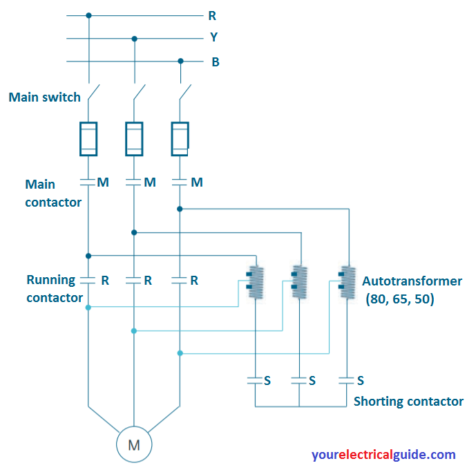
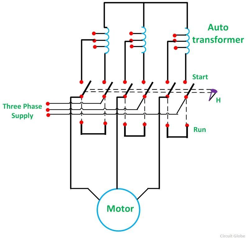
Drawing the schematic diagram of automatic voltage regulators of AC. Simplex Lap Wave winding with brush position. Schematic of an auto transformer starter is shown below.
519 56 kb transformer wiring diagram a. Squirrel cage induction motor started on full line voltage using D O L starter as a starting method draw very large starting current which can damage motor winding and also create a current surge on the power system. Q2A Draw the schematic diagram for an Autotransformer Starter for a Three Phase Induction Motor.
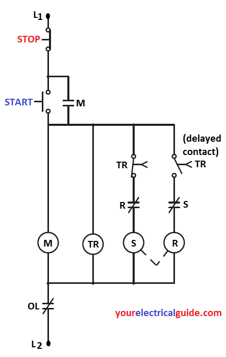
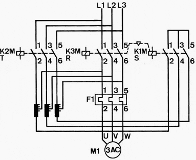
3 Winding Drawing the development diagram for DC. Drawing the schematic diagram of AC. There are three main contactors that play critical role in auto transformer reduced voltage starting.
The above diagram depicts the connections of the loaded step-down and step-up autotransformer. 2 Alternator Tracing of panel wiring diagram of an alternator. It can be proved mathematically that the weight of copper required in an autotransformer W a will be.
Draw The Schematic Diagram Of Autotransformer Starter. DOL Starter Wiring Diagram. Star Delta Starter Circuit Diagram.
Circuit diagrams Autotransformer part winding Autotransformer HOA An autotransformer starter reduces inrush current by using a transformer in the line just ahead of the motor to step down the voltage applied to the motor terminals. This is a big advantage of a star delta starter as it typically has around 13 of the inrush current compared to a DOL starter. 1124 58 kb transformer wiring diagram m0n acme.
Simplex Lap Wave winding with brush position. 2 Alternator Tracing of panel wiring diagram of an alternator. A direct online starter consists of two buttons a GREEN button for starting and a RED for stopping purpose of the motor.
Hence another starting method is used to start three phase induction motor called an autotransformer starter. 2 Alternator Tracing of panel wiring diagram of an alternator. The starting method or starter are used according to the size of the motor.
Working Principle of a Transformer. Drawing the schematic diagram of AC. 3 Winding Drawing the development diagram for DC.
They are the start contactor S main contactor M and the run contactor R. Does Magnesium Interact With Blood Pressure Medication. Saving W o W a.
3 Winding Drawing the development diagram for DC. The DOL starter comprises an MCCB or circuit breaker contactor and an overload relay for protection. The equivalent circuit diagram of transformer is given below-Where R 1 Primary Winding Resistance.
Where W a weight of Cu in autotransformer W o weight of Cu is an ordinary transformer K transformation ratio. Desember 20 2021 Posting Komentar Korndorfer starter with mot Baca selengkapnya Draw The Schematic Diagram Of Autotransformer Starter. We use it to reduce the starting current of the motor without using any external device or apparatus.
Motor speed control by SCR AC Drive. Saving K W o. Motors of these power ratings draw excessive starting current with the use of StarDelta starter.
Drawing the schematic diagram of AC. Drawing the schematic diagram of automatic voltage regulators of AC. By reducing the voltage the current drawn from the line is reduced during start-up.
Autotransformer Starter Diagram Parts Working Principle. Motor speed control by SCR AC Drive. Component 1 2 3 3 4 5 c Write the relationship between line currents of the motor and the line at start.
For example DOL starter or Direct On Line Starter is used for the starting of low size or. Motor speed control by SCR AC Drive. The starter mainly consists of a TPDP switch which.
506 90 kb transformer wiring diagram d. 2 Alternator Tracing of panel wiring diagram of an alternator. Drawing the schematic diagram of automatic voltage regulators of AC.
Drawing the schematic diagram of Autotransformer starter DOL starter and Star Delta Starter. Drawing the schematic diagram of AC. The wiring diagram for a DOL stater is shown below.
W a 1 K W o. Desember 19 2021 Posting Komentar. 1124 49 kb transformer wiring diagram l.
V 1 is the supply voltage per phase. Operation of a practical autotransformer starter. This may cause excessive strain on the motor and creates an intense voltage dip.
Figure a shown below represents the condition when the motor is directly switched on to lines and figure b shows when the motor is started with the help of an autotransformer. In both cases I 1 is the input current and I 2 is output current Regardless of Step UpStepdown autotransformer the current in the section of winding that is common to both the primary and secondary is the difference between these two currents I 1 and I 2. Auto transformer Starter can be used for.
Simplex Lap Wave winding with brush position. Motor speed control by SCR AC Drive. Motor speed control by SCR AC Drive.
929 49 kb transformer wiring diagram c. Drawing the schematic diagram of automatic voltage regulators of AC.

Auto Transformer Starter Your Electrical Guide

Drawing The Schematic Diagram Of Autotransformer Starter Dol Starter And Star Delta Starter Youtube

Auto Transformer Starter Your Electrical Guide

Starting Motor With Auto Transformer

Korndorfer Autotransformer Starter Wikipedia

Autotransformer Starter Circuit Globe

What Is Auto Transformer Starter Working Principle Diagram Advantages
0 comments
Post a Comment